Abstract: This article describes the welding method, strength testing, upper and lower stem hole machining, and chip prevention measures for the body assembly of a single-seam fully welded trunnion ball valve.
The body of a single-seam fully welded trunnion ball valve is formed by welding together two spherical crown-shaped sections. The central weld seam is positioned away from the valve seat to minimize the effect of welding on the seat’s non-metallic components, while reducing both the total number of welds and the risk of leakage. As a result, single-seam fully welded trunnion ball valves are extensively used in long-distance pipelines, particularly for transporting natural gas and crude oil.
The single-seam fully welded trunnion ball valve body (hereinafter referred to as the valve body) is difficult to repair after welding, especially after the upper and lower trunnion bearing seats have been welded. Therefore, strict control of the machining process during manufacturing is essential to ensure that the valve body achieves welding quality standards in a single pass.
After the left and right valve bodies are welded together (Figure 1), a sealing test must be performed. Without upper and lower trunnion supports inside the valve body, the ball and valve seat float freely within the cavity. During a sealing test on one end, the inlet-side valve seat is pushed toward the opposite end. Consequently, the inlet media force is fully borne by the sealing surface of the outlet-side valve seat. However, the specific pressure at the outlet sealing surface—calculated based on the difference in active area between the valve seat and piston ring—can exceed the material’s allowable specific pressure by several times, potentially causing deformation or collapse of the outlet sealing surface. To prevent this, auxiliary fixtures (Figure 2) should be installed during assembly—before welding the valve body—to secure the ball in position and enable sealing performance testing.
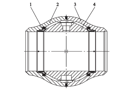
1. Valve seat assembly 2. Left valve bodies 3. Right valve bodies 4. Balls
Figure 1 Left and right valve body welding
The auxiliary fixture is a four-piece core-pulling trunnion assembly (Figure 3), comprising two separate upper and lower core-pulling shafts and four quarter rings. The assembly is installed in symmetrical holes on the left and right valve bodies, aligned coaxially with the upper and lower trunnion bearing seats. The core-pulling shafts are coaxial with the quarter rings and can rotate freely within them. The upper core-pulling shaft is mechanically connected to the ball, enabling it to rotate about the axis of the quarter ring assembly. The four quarter rings are cut in parallel pairs. In cross-section, the length a of quarter rings 2 and 3 is shorter than the length b of the core-pulling shaft, while the chord length c of quarter rings 1 and 4 is smaller than the diameter of the upper and lower trunnion holes. The outer diameters of the upper and lower core-pulling shafts are smaller than those of the corresponding trunnion holes. In use, the four-piece core-pulling trunnion assembly serves as a temporary auxiliary trunnion for the ball, supporting the sealing test load after the left and right valve bodies are welded together.
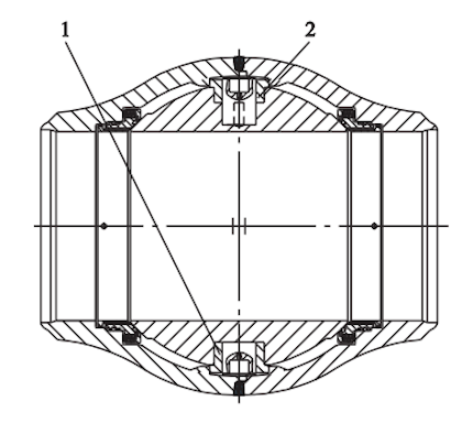
1. Lower Quarter Core-Pulling Shaft 2. Upper Quarter Core-Pulling Shaft
Figure 2 Auxiliary fixtures
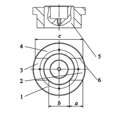
1. Quarter Ring 1 2. Quarter Ring 2 3. Quarter Ring 3 4. Quarter Ring 4 5. Core-Pulling Shaft 6. Parallel Cuts
Figure 3 Four-piece core-pulling trunnion assembly
The valve body assembly is welded with a single narrow central weld performed in multiple passes. Before welding, the left and right valve bodies are aligned with the upper and lower trunnion axes, using the valve stem axis as a reference. During assembly, ensure precise alignment and positioning of the left and right valve bodies relative to the upper and lower trunnion axes. Once aligned, the valve body should be securely tack-welded. With the ball in the closed position, a low-pressure leak-tightness test is performed using orifice sealing plugs and a double-ended tightening test bench. Once the test is passed, welding proceeds following the approved welding procedure. The root pass is completed using Gas Tungsten Arc Welding (GTAW) to prevent slag formation and ensure high-quality welds. For horizontal end supports on medium- and large-diameter valves, the valve’s own weight and its effect on the bending stress of the root welds should be considered. The second and third passes are also performed using Gas Tungsten Arc Welding (GTAW), while subsequent passes employ Submerged Arc Welding (SAW). A low-current, multi-pass welding approach is adopted, with careful control of heat input to minimize welding stress and deformation of the valve body, thereby preventing valve seat seizure. After welding is completed, the valve body forms a single integrated piece. A temporary hole (“A”) is then machined at the valve stem position to enable installation of an operating lever for a no-load open/close cycle (Figure 4).
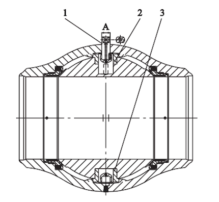
1. Temporary operating lever 2. Upper quarter-core pull-out trunnion shaft 3. Lower quarter-core pull-out trunnion shaft
Figure 4 Temporary hole “A” in the valve body
After welding, the temporary hole “A” is used to mount the temporary operating lever onto the upper pull-out trunnion shaft. The lever is turned to drive the ball through a no-load open/close cycle. During this test, verify smooth valve operation, check for any sticking, and ensure the ball orifice does not damage the sealing surfaces during movement. Upon completion of the no-load test, conduct high-pressure hydrostatic testing and low-pressure pneumatic sealing tests using orifice sealing plugs and a double-ended test bench.
Although the symmetrical reference center point for the trunnion shaft position is established before welding the left and right valve bodies, the valve body’s spherical geometry, central weld seam, and welding-induced stress and deformation limit its use to a positional reference for the upper and lower trunnion bearing seat holes. It cannot be used as a reference for the precision boring and alignment of the upper and lower trunnion shaft holes. The machining accuracy of these holes directly affects the valve’s sealing performance. After the valve body passes the sealing performance test, the weld between the upper and lower trunnion bearing seats and the valve body is bored at location B. When boring hole B, a smaller pilot hole (B′) is first rough-bored, then aligned using hole C on the upper and lower mandrels as a reference. Hole B is subsequently finish-bored to its final size, chips are removed, and the upper and lower trunnion bearing seats are assembled to the valve body (Figure 5). After welding and inspecting the upper and lower trunnion bearing seats, the upper and lower trunnion shaft holes are finish-bored, again using hole C on the upper and lower mandrels as the reference (Figure 6). When drilling the trunnion bearing seat holes and finish-boring the welded valve body, precautions must be taken to prevent chips from entering the valve cavity and damaging the sealing surfaces. A pot-lid-shaped drilling method is recommended: calculate the cutting depth based on the hole size at the opening point, and when the remaining wall thickness reaches approximately 0.5 mm, remove the entire section with a hammer. For ferromagnetic materials, a magnet can be attached to the cutter head. After drilling, a non-fragmenting, easily removable, flexible filler should be placed between the quarter-core trunnion shaft and the valve body.
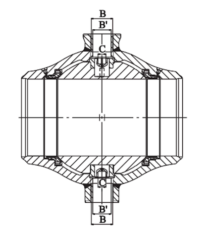
Figure 5 Welding the Upper and Lower Trunnion Bearing Seats to the Valve Body
After machining the upper and lower trunnion shafts, remove chips from the quarter-core pull-out trunnion shaft. Blow dry air into the holes before assembly, positioning the chip removal openings as far downward as possible. Take precautions to prevent the pull-out shaft from being ejected unexpectedly.
Before assembling the upper and lower trunnion shafts, remove the auxiliary fixtures (quarter-core pull-out trunnion shafts). When removing them, tilt the exposed end downward to facilitate the discharge of any remaining metal chips. First, remove the pull-out shaft. Then, slide quarter rings 2 and 3 horizontally toward the center of the pull-out shaft hole, followed by quarter rings 1 and 4. Finally, blow compressed air from top to bottom to clear away any chips. After blowing, move to the opposite side and remove the other quarter-core pull-out trunnion shaft.
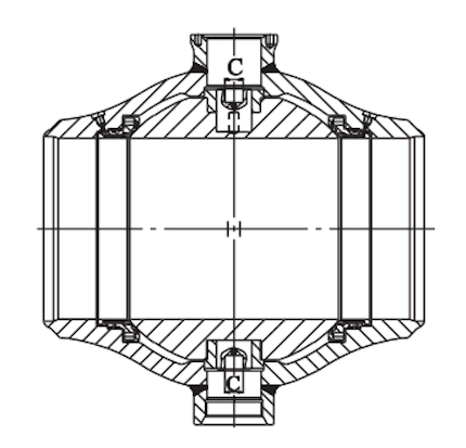
Figure 6: Completed upper and lower trunnion shaft holes
The single-seam, fully welded trunnion-mounted ball valve body incorporates an auxiliary machining process using an internal four-part core-pulling trunnion shaft. This design enhances machining efficiency and improves the first-pass yield of finished products.