Abstract: This paper presents a pneumatic shut-off ball valve developed for a BDO efficiency improvement and energy optimization project, detailing its structural features, operating conditions, process parameters, and working principle. Based on the operating and process conditions, the ball valve has been structurally optimized to prevent metal-to-metal wear of the valve stem, reduce the risk of excessive stem torque and stiff operation, and improve overall valve performance and service life.
1,4-Butanediol (BDO) is an important and widely used chemical raw material. Energy efficiency improvement projects for BDO aim to reduce energy consumption and pollutant emissions, representing a highly effective, energy-saving, and environmentally friendly technological approach. The medium in the BDO reactor is a gas–solid or liquid–solid two-phase mixture. The catalyst added to the system tends to self-polymerize and may accumulate in the gaps between valve components, leading to valve jamming and pipeline blockage. Moreover, the catalyst is toxic—it can cause mild anesthesia upon minor exposure and lead to nerve paralysis or even death in severe cases—making tight valve sealing essential. The combined tail gas from the BDO enrichment tower and the butanediol tail gas, after flaring, must be discharged or flushed through the pipeline in sequence. On average, the valve operates about once every five minutes, with each actuation completed in under three seconds. Consequently, the valves must be capable of high-frequency operation, ensuring rapid, reliable switching and shut-off performance. The optimized three-way reversing ball valve provides significant advantages when handling media with high solid content, such as in the coking and crystallization stages of BDO additive production. Based on the valve’s operating conditions and process requirements, its structure has been optimized to deliver a pneumatically actuated, high-frequency three-way reversing ball valve with stable operation, low torque, and reliable performance for rapid switching and frequent cycling.
structure of the pneumatic high-frequency three-way reversing ball valve is shown in Figure 1. The valve incorporates a top-mounted ball and a forged steel body fastened with four-sided seat bolts. The forged steel body provides superior mechanical properties and enhanced stability, fully meeting demanding operational requirements. The ball valve features a three-way (L-type) full-bore flow channel, with fixed upper and lower shaft supports and a symmetrical four-sided SPE metal floating seat design. This design eliminates lateral imbalances caused by medium pressure in the three-way reversing ball valve. The valve seat features a sharp scraper for self-cleaning, along with SPE double-blocking and self-relieving pressure functions. The ball and valve seat surfaces are hardened to enhance wear and scratch resistance. They are precisely matched and ground to achieve a tight fit, ensuring reliable sealing performance. The four-sided valve seat design keeps the sealing surface in constant contact with the ball, minimizing erosion from the medium and further improving sealing reliability.
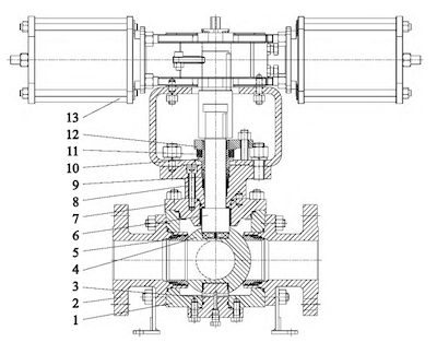
- Valve body
- Connector
- Fixed shaft
- Ball
- Valve seat
- Valve stem
- Valve bonnet
- Gland flange
- Packing assembly
- Packing sleeve
- Disc spring
- Packing pressure plate
- Pneumatic actuator
Figure 1 Pneumatic high-frequency three-way reversing ball valve
Nominal diameter: NPS 3″
Pressure rating: Class 300
Temperature: 93 °C
Maximum differential pressure: 1.725 MPa
Process medium: BDO (1,4-Butanediol)
For the L-type, full-bore, four-way three-way reversing ball valve, the medium flow direction, air supply failure points, full-stroke times, and operating frequency are specified as follows:
Flow Direction
As shown in Figure 2, the medium flow direction during normal operation and in the event of instrument air failure is illustrated in Figure 2a (PRODUCT). During backflushing, the medium flow direction is shown in Figure 2b (BLOWBACK).
Operating Frequency
The valve operates once every 30–600 seconds in the sequence PRODUCT → BLOWBACK → PRODUCT. During each operating cycle, it remains in the BLOWBACK state for approximately 1.5 seconds.
Actuation Time
The transition from BLOWBACK → PRODUCT occurs in less than 1.5 seconds, while the transition from PRODUCT → BLOWBACK takes approximately 3 seconds.
The L-type three-way ball valve operates by rotating the ball to redirect the medium flow, thereby opening or closing the valve. This type of valve connects only two mutually perpendicular pipelines at a time and serves primarily as a flow distribution device.
The operating principles are as follows:
- When port C serves as the inlet, the valve can switch the flow between C → B or C → A. However, port C cannot function as a shut-off port; otherwise, neither port B nor port A can be completely closed.
- When port C serves as the inlet, the valve can switch the flow between C → B or C → A. However, port C cannot function as a shut-off port; otherwise, neither port B nor port A can be completely closed.
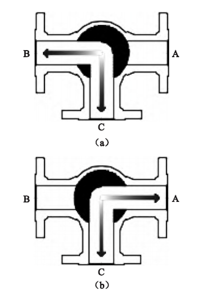
Figure 2 The flow directions
The valve adopts an integral valve seat structure. Between the valve seat and the connector are installed a flexible graphite ring, spring seat, wave spring, pressure ring, and graphite dustproof ring. This configuration prevents particulate-laden media from entering the valve cavity through the sealing rings formed at the front and rear ends of the valve seat, thereby protecting other components from erosion. The valve seat adopts a full-bore flow channel with a smooth, curved design that eliminates dead zones, making it suitable for handling multiphase media such as suspensions, dust, particulates, and catalysts. A wave spring is positioned between the spring seat and the pressure ring. At the front end, the spring seat delivers an elastic thrust to the valve seat, ensuring initial sealing and effective performance under low to medium pressure, while also compensating for sealing surface wear to maintain long-term sealing between the ball and valve seat. At the rear end, the pressure ring applies elastic thrust to ensure a tight seal between the dustproof ring and the connecting body, preventing the medium from entering the valve seat cavity. The sealing interface between the valve seat and the connecting body comprises an O-ring and a flexible graphite ring. The front-end O-ring functions both as a primary seal and as a dust barrier, safeguarding the flexible graphite ring. Sealing is accomplished by the spring seat compressing the flexible graphite ring under the force of the spring. To enable deformation and ensure effective sealing, the graphite ring is designed as a stepped conical structure with two distinct angles, and the corresponding valve seat is similarly stepped with complementary angles. The angular mismatch at the mating point converts the axial thrust into an oblique compressive force, enhancing the sealing pressure at the contact area and improving overall sealing performance. To minimize media buildup and scaling, the valve seat sealing surface features smooth, rounded transitions. The valve has a sharp, knife-edge-shaped sealing surface that scrapes the spherical ball during opening and closing, providing a self-cleaning function. Smooth, rounded transitions on both sides remove dead zones and prevent the accumulation of media. A protected spring structure is incorporated to enhance sealing, and the dust ring is configured in a double-cone, self-tightening design. The mating surfaces of the pressure ring and connecting body are angled to achieve a double-cone, self-tightening seal. Combined with the spring thrust, this design ensures both effective sealing and dust protection. Figure 3 shows the valve seat and dustproof structure.
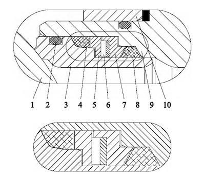
1. Ball 2. O-ring 3. Valve seat 4. Flexible graphite ring 5. Spring seat 6. Wave spring 7. Pressure ring 8. Graphite dustproof ring 9. Connector 10. Valve body
Figure 3 Valve seat structure and dustproof assembly
The valve stem is treated with surface hardening and reinforced with hard-alloy spray or overlay welding, giving it high hardness and excellent wear resistance. This treatment minimizes the risk of scratches during valve closure. The valve stem is machined to a surface roughness of ≤0.4 μm, effectively reducing operating torque and extending service life. The valve stem, valve bonnet, gland flange, and packing sleeve are all designed with clearance fits to avoid direct metal-to-metal contact, reducing friction and further lowering operating torque. The valve stem is guided and supported by a three-section sliding bushing system (bushings I, II, and III), ensuring precise positioning, minimizing stem offset, and enabling smooth torque transmission.
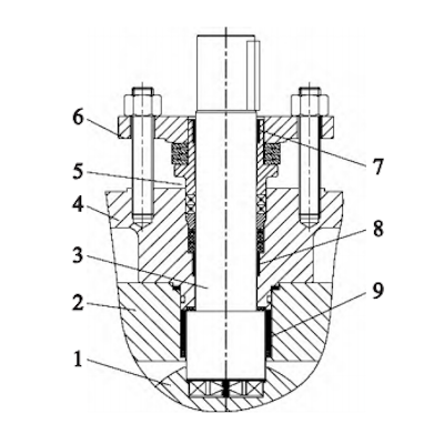
- Ball
- Bonnet
- Stem
- Gland Flange
- Packing Gland Sleeve
- Packing Gland Plate
- Sliding Bushing I
- Sliding Bushing II
- Sliding Bushing III
Figure 4 The valve stem support and guiding structure
The packing seal features a spring-loaded, adjustable compensation design. A disc spring, guided by an extension of the packing sleeve, is installed between the packing sleeve shoulder and the packing pressure plate, providing dynamic load compensation for the packing assembly. Leveraging the spring’s stored elastic energy, the system automatically compensates for packing loosening, volume changes, or reductions in the contact force between the valve stem and the packing, maintaining effective sealing. This design maintains consistent sealing performance and prevents seal failure. The valve stem seal employs a packing assembly composed of V-PTFE packing, a packing gasket, and flexible graphite packing, with V-PTFE serving as the primary sealing material. Its self-lubricating properties minimize valve stem wear. The assembly also features a fire-resistant design, with the stepped stuffing box providing a double packing seal. In the event of a fire, the flexible graphite packing deforms under the pressure of the disc spring, maintaining the seal and ensuring fire resistance. The packing sleeve adopts an extended design, with the disc spring positioned outside the extension—between the packing sleeve shoulder and the packing pressure plate. This configuration prevents uneven axial loading caused by lateral spring movement and protects the valve stem surface from scratches. The outer diameter of the extended sleeve section ensures accurate guidance of both the disc spring and the packing plate. Inside the packing sleeve, sliding bushing I guides the valve stem and prevents direct metal-to-metal contact, further reducing wear. The height of the extended sleeve is designed to ensure that the stacked disc springs remain fully contained within the packing plate during operation.
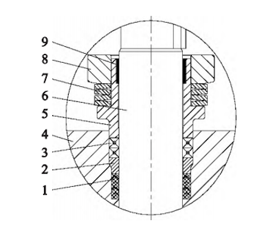
- V-PTFE packing
- Packing gasket
- Graphite packing
- Gland flange
- Packing sleeve
- Valve stem
- Disc spring
- Packing gland
- Sliding bushing
Figure 5 The packing seal structure
As shown in Figure 6, the ball adopts a valve stem and fixed-shaft support configuration to maintain precise axial centering and positioning. This design effectively prevents axial displacement of the ball caused by the pressure of the medium. The valve stem head features an integrated cylindrical and drive section that extends directly into the ball, serving both positioning and driving functions. The polygonal connection provides a large contact area, minimizing compressive stress at the connection interface and allowing for efficient high-torque transmission. To prevent particles from entering and damaging the valve stem and bushing surfaces—which could shorten service life, increase transmission torque, or even cause valve jamming—a dustproof ring is installed at the lower end of the sliding bushing. Additionally, an electrostatic spring located at the valve stem head dissipates static charges generated by the ball’s rotational friction through the valve body to the pipeline, ensuring an anti-static function. The fixed shaft serves as the main load-bearing component at the bottom of the valve, supporting the ball and its weight. An adjusting shim mounted on the fixed shaft enables precise alignment of the ball’s flow channel center by varying the shim thickness. A sliding bearing installed on the fixed shaft ensures smooth and flexible rotation of the ball. Additionally, an annular mounting groove on the fixed shaft accommodates an O-ring, preventing small particles from entering the ball support hole. This protects the fixed shaft and sliding bearing, prevents increased torque, and ensures smooth, responsive rotation of the valve ball.
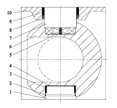
- Fixed shaft
- O-ring
- Sliding bearing
- Adjusting shim
- Static spring
- Ball
- Valve stem
- Dust seal
- Sliding bushing
- Valve bonnet
Figure 6: Ball fixing structure
Figure 7 shows the O-ring and metal spiral-wound gasket structures used for sealing and fire protection at the interfaces between the valve body and connecting body, valve body and valve cover, and valve cover and gland flange. The combined O-ring and metal spiral-wound gasket dual seal minimizes static leakage at valve connections, effectively enhancing the overall performance of the valve. Under normal operating conditions, the O-ring functions as the primary seal. In the event of a fire, should the O-ring fail, the spiral-wound gasket takes over as the main sealing element, ensuring fire-resistant protection. An annular groove is machined into the valve body to securely house and compress the spiral-wound gasket, ensuring effective deformation and reliable sealing. This groove also safeguards the gasket during assembly and disassembly, preventing damage during maintenance.
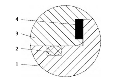
- Connected parts
- O-ring
- Valve body
- Spiral-wound gasket
Figure 7: Connection and sealing structure
The optimized design of the pneumatic high-frequency three-way reversing ball valve effectively prevents metal-on-metal wear of the valve stem, reducing the risk of high stem torque and stiff rotation. These enhancements improve both valve performance and service life. Consequently, the valve ensures safe, reliable, and stable operation of the BDO unit’s backflushing and discharge systems, fully meeting the demands of high-frequency switching and harsh process conditions.