Abstract: This paper provides an overview of the manufacturing and inspection technologies employed in the production of fully welded ball valves, with a particular emphasis on fabrication and welding processes. In recent years, driven by changes in the energy structure and regional energy strategies, China’s oil and natural gas pipeline networks have developed rapidly. In major projects such as the first and second lines of the West–East Gas Pipeline, a large number of the switching and regulating valves used are fully welded ball valves, which are widely adopted internationally and recognized for their technical maturity. Driven by growing domestic demand, fully welded ball valve technology in China has made significant advancements. At the same time, China’s pipeline systems impose strict requirements on pressure resistance, materials, and environmental conditions, thereby raising the technical standards for fully welded ball valves. Currently, the key performance requirements for ball valves used in long-distance pipelines include uniform stress distribution, reliable sealing, a compact structure, lightweight design, and high strength. This paper outlines the manufacturing processes and welding techniques used in the production of fully welded ball valves, with the aim of supporting continued development and innovation within the industry.
The fully welded ball valve discussed in this paper features a spherical body with a single weld seam and is manufactured using fully automated welding processes. These valves offer several advantages, including uniform stress distribution, excellent sealing performance, compact construction, reduced weight, and high mechanical strength. Combining technical reliability with economic efficiency, fully welded ball valves are widely used both in China and internationally. Their widespread adoption signifies a shift away from the traditional cylindrical designs that once dominated China’s pipeline valve market.
The structure of the fully welded ball valve described in this paper is shown in Figure 1. The most notable difference between this design and that of a traditional three-piece ball valve is the welded body, which replaces mechanical joints with a fully sealed weld. As a result, both the internal and external linings play a crucial role during the welding process. Additionally, the valve is installed onto the pipeline by welding. The valve seat typically uses a double-seal design, providing sealing on both the upstream and downstream sides. The embedded sealing ring in the valve seat offers excellent corrosion resistance, wear resistance, and elasticity, ensuring high sealing performance. The structure of the valve seat is shown in Figure 2, and the operating principle of the double-seal valve seat is explained as follows:
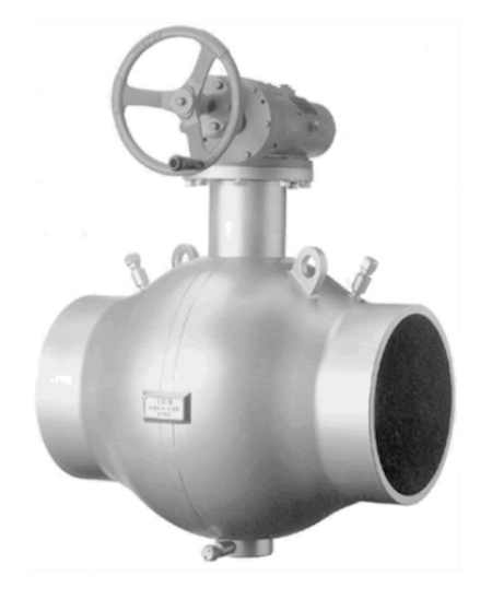
Figure 1 Fully welded ball valve
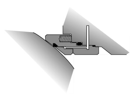
Figure 2 Valve seat structure
(1) Upstream Valve Seat Sealing Principle:
Under upstream pressure, the valve seat is pressed against the ball to form a seal, as shown in Figure 3. The force acting on the valve seat (F) is calculated as:
F = p + F_s
where p is the pipeline pressure and F_s is the spring force.
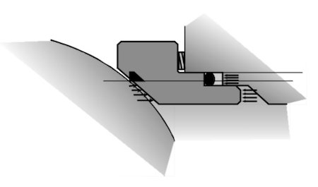
Figure 3 Upstream sealing principle
(2) Downstream Valve Seat Sealing Principle:
Due to the internal pressure within the valve body, the downstream valve seat is also pushed against the ball to form a seal, as illustrated in Figure 4. The force acting on the downstream valve seat (F) is given by:
F = π(D₁² - D₂²)p + F_s
where p is the pipeline pressure, and F_s is the spring force.
The valve stem is sealed with a G-T ring—a composite of fluororubber and polytetrafluoroethylene—that provides excellent anti-rotation properties and forms a dual seal at both the upper and lower ends. Additionally, emergency sealing grease can be injected between the double sealing rings to provide temporary sealing in case of leakage. The valve stem sealing structure is shown in Figure 5.
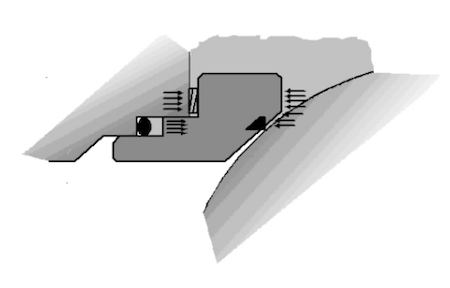
Figure 4 Downstream sealing principle
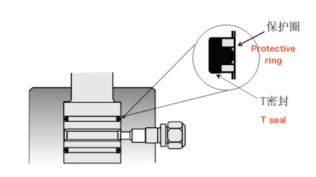
Figure 5 Valve stem seal structure
If the valve seat requires emergency repair, it can be serviced as shown in Figure 6 without compromising the welded structure. Static electricity generated by internal components, such as the ball and valve seat ring, is discharged to the valve body through a spring and gasket. From an operational standpoint, the valve is easy to operate because the trunnion support reduces the required operating force. The trunnion is equipped with a low-friction polytetrafluoroethylene (PTFE) bearing. The valve employs a floating seat design, so the force exerted on the seat by the ball is relatively low compared to the fluid pressure.
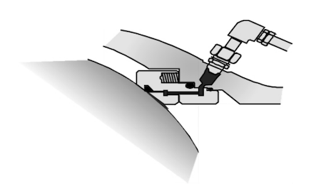
Figure 6 Schematic Diagram of Emergency Valve Seat Repair
In terms of maintenance, ball valves generally require minimal servicing. If leakage occurs in the sealing area, sealing grease can be injected for temporary repair. For emergency repairs of the valve seat or valve stem seals, IKSS-3L sealing grease should be used.
(1) The valve body is primarily made from forged materials.
(2) The ball is also manufactured from forgings and undergoes surface treatment.
(3) The valve seat ring is made from 18Cr-8Ni stainless steel forgings.
(4) The valve stem requires surface treatment.
(5) The sealing materials mainly consist of nitrile rubber and epichlorohydrin rubber.
The welding process for fully welded ball valves is fully automated.
Valve Body Welding: GTAW (Gas Tungsten Arc Welding) combined with SAW (Submerged Arc Welding)
Valve Stem Welding: GTAW (Gas Tungsten Arc Welding) combined with GMAW (Gas Metal Arc Welding)
Pipe Welding: GTAW (Gas Tungsten Arc Welding) combined with SAW (Submerged Arc Welding)
Since fully welded ball valves are directly integrated into the pipeline through welding, their inspection requirements differ from those of conventional valves.
The bending test simulates pipeline deformation caused by uneven ground settlement. The test procedure is shown in Figure 7.
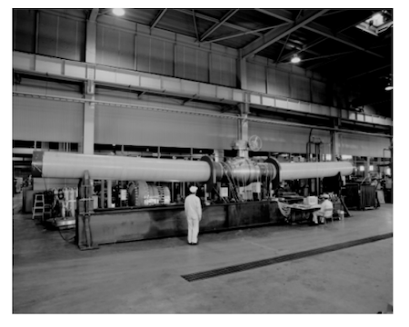
Figure 7: Bending Test Procedure
Test Method:
Connect the valve to the pipeline and apply a bending moment of 4200 kN·m.
Measure the stress on both the valve and the pipeline.
Test the valve’s sealing performance under the nominal working pressure using air as the test medium.
Measure the valve’s opening and closing torque.
Acceptance Criteria:
The stress in all valve components must remain below the material’s yield strength.
No external leakage or seat leakage is permitted.
The operating torque must stay within normal limits without any abnormalities.
The tension and compression test procedure is illustrated in Figure 8.
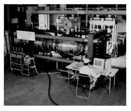
Figure 8: Valve Tension and Compression Test Procedure
Test Method:
(1) Apply tensile and compressive forces of 19,900 kN to the pipeline connected to the valve.
(2) Apply internal air pressure between 0.4 and 0.7 MPa to measure external leakage, seat leakage, and deformation (twisting).
(3) Measure the stress levels on both the valve and the sleeve.
Acceptance Criteria:
The stress in all valve components must remain below the material’s yield strength.
No external or seat leakage is allowed.
The operating torque must remain stable and free of abnormalities.
The flushing test simulates the oil and gas transportation process. The test setup is shown in Figure 9.
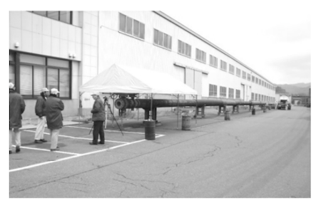
Figure 9: Flushing Test Site
Test Method:
Inject nitrogen at the nominal working pressure into the piping of the flushing test apparatus.
Open the valve to allow fluid to pass through and flush the valve seat.
Inspect the valve seat for any abnormalities.
Acceptance Criteria:
No abnormalities are observed on the valve seat.
The sealing performance of the valve seat remains stable and defect-free.
This test simulates the valve’s operating conditions and evaluates its durability under repeated cycles.
Test Method:
Close the valve and apply air pressure at the nominal working pressure to the valve seat, then fully open the valve. Repeat this cycle 200 times.
Inspect the valve seat for leakage under air pressures ranging from 0.4 to 0.7 MPa as well as at the nominal working pressure.
Acceptance Criteria:
No leakage is detected from the valve seat.
The valve seat shows no abnormalities.
This test simulates valve operation during the extremely cold winters typical of Northwest and Northeast China.
Test Method:
Cool the ball valve to –45°C and perform 200 opening and closing cycles.
After cycling, inspect the valve seat for leakage under air pressure ranging from 0.4 to 0.7 MPa, as well as at the nominal working pressure.
Acceptance Criteria:
No leakage is detected from the valve seat.
The valve seat exhibits no abnormalities.
This test simulates the presence of foreign objects during oil and gas transportation and verifies that the ball valve can continue to operate normally under such conditions.
Test Method:
Introduce 100 mL of a mixture of sand, rust, and oxide scale of varying mesh sizes at the contact interface between the valve seat and the ball.
Perform 250 opening and closing cycles.
After every 50 cycles, inspect the valve seat for leakage at air pressures of 0.6 MPa and 7 MPa.
Inject sealing grease into the valve seat and conduct an emergency sealing test.
Acceptance Criteria:
No valve seat leakage after 150 cycles.
Leakage not exceeding 180 mL/min after 200 cycles.
Leakage not exceeding 625 mL/min after 250 cycles.
No valve seat leakage after sealing grease injection.
Stable operating torque and smooth valve operation.
3.7 Blowing Test
Test Method:
Close the valve, place 1 liter of foreign material in front of the valve seat, apply 7 MPa of air pressure to the side containing the foreign material, open the valve to 16%, and blow the foreign material into the valve seat.
Perform a valve seat leakage test at air pressures of 0.6 MPa and 7 MPa.
Acceptance Criteria:
No leakage from the valve seat and no abnormalities in operating torque.
To simulate seismic conditions, the ball valve is subjected to varying loads, amplitudes, and frequencies on a vibration test bench.
Test Method:
Apply a load to the extension rod to simulate the hydraulic bending force generated by foundation movement.
Measure the stress on both the valve and the extension rod.
Perform a sealing test at a pressure of 11.3 MPa.
Conduct an operating torque test.
Acceptance Criteria:
The stress in all components must remain below the material’s yield strength.
The valve must exhibit no leakage or abnormalities.
The operating torque must remain within normal operating parameters.
The fully welded ball valve with a spherical structure offers several advantages, including uniform stress distribution, a compact design, reduced weight, and high structural strength. The double-piston effect valve seat, combined with specially formulated sealing rubber, significantly enhances sealing reliability and ensures a service life of up to 30 years. Comprehensive testing confirms that the valve meets all performance requirements under a wide range of special operating conditions.