Abstract: The performance of low-temperature, large-diameter, high-pressure, top-entry trunnion-mounted ball valves is primarily influenced by seat seal leakage, micro-leakage at the central flange joint, stem packing leakage, and leakage at the valve cavity bleed port connection. Failure to adequately address these factors during design may result in serious safety risks, especially affecting sealing stability and installation ease. To ensure long-term, reliable operation in pipeline systems, simulation analysis and structural optimization should be integrated from the design and development stages. Low-temperature, large-diameter, high-pressure, top-entry trunnion-mounted ball valves play a critical role in quality control for facilities such as LNG plants, receiving terminals, regasification stations, coal gasification and air separation units, and coal-to-olefins projects. Currently, ultra-low-temperature ball valves, particularly those with pressure ratings of 15–25 MPa, are predominantly imported. Imported high-pressure, large-diameter, top-entry ball valves are not only expensive but also have long lead times. Moreover, once critical components are damaged, they cannot be rapidly replaced or repaired, severely limiting the stable operation of the equipment. Consequently, domestic production of these valves is of strategic importance. However, an analysis of the current domestic landscape indicates that localization still faces significant challenges:
Technical Challenges: These include gaps in design technology compared with foreign manufacturers, lower reliability in valve design, limited research on low-temperature material selection, and insufficient analysis of sealing performance under cryogenic conditions.
Manufacturing Challenges: Domestic companies entered the ultra-low-temperature valve sector relatively late and therefore lack both theoretical research and practical experience in component machining, product assembly, and tolerance selection and matching. Significant foundational work remains necessary. This paper presents a design analysis of an NPS 16 Class 1500 low-temperature, large-diameter, high-pressure, top-entry trunnion-mounted ball valve.
The reliability of low-temperature valves is assessed using Failure Mode and Effects Analysis (FMEA). Identified failure modes and their causes are analyzed to determine weak points, and corresponding improvement measures are proposed.
Table 1. Summary of Component Failure Modes
|
Component |
Failure Mode |
|
Valve Body |
Wall thickness deviation; strain in sealing area under load |
|
Valve Seal Assembly |
Deformation under stress; uneven shrinkage at low temperatures |
|
Valve Stem |
Insufficient strength; stiffness or deflection issues |
|
Flange Connection |
External leakage at flange joint |
|
Packing |
External leakage at stuffing box |
The valve body is the primary structural component of the valve. Finite element analysis (FEA) was performed to verify that the valve body wall thickness meets design requirements (Figure 1) and to ensure that stress and strain levels in all sealing areas remain within specified limits.
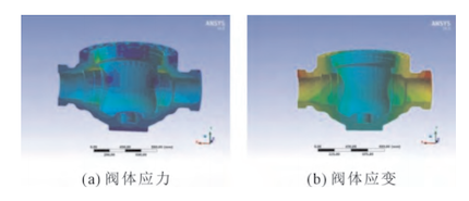
Figure 1. Stress–strain contour of the valve body: (a) stress distribution, (b) strain distribution
For this large-diameter, high-pressure valve, ensuring the sealing reliability of the bonnet-to-body connection is essential. Therefore, the strength of the center flange must be rigorously ensured. Finite element analysis (FEA) was conducted to verify compliance with design requirements (Figure 2).
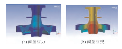
Figure 2. Bonnet stress–strain contours: (a) stress distribution, (b) strain distribution
1.3 Simulation Analysis of Seat–Ball Sealing Pair Strength and Sealing Surface Pressure Response at Low Temperatures
At −196 °C, thermal contraction of the components leads to changes in their dimensional parameters. Consequently, the uniformity of the sealing surface pressure and the coordinated thermal contraction of components under cryogenic conditions directly influence the valve’s sealing performance. Using thermal–structural coupled analysis, the stress–strain state of the sealing pair was evaluated (Figure 3) to verify that the dimensional parameters meet the sealing requirements. The distribution of the sealing surface pressure is shown in Figure 4.
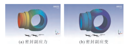
Figure 3. Stress–strain contours of the seal pair: (a) stress distribution, (b) strain distribution
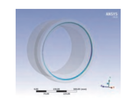
Figure 4. Contour of specific pressure distribution on the sealing surface
The bonnet and stem are sealed with a combination of soft, flexible graphite and high–molecular-weight polytetrafluoroethylene (PTFE) packing. To ensure reliable sealing performance, the packing must maintain sufficient resilience; therefore, its operating temperature should be kept above 0 °C. ANSYS temperature field analysis was conducted to verify that the extended bonnet height meets the design requirements (Figure 5). Table 2 compares the extended bonnet height requirements for NPS 16 valves specified in various cryogenic valve standards.
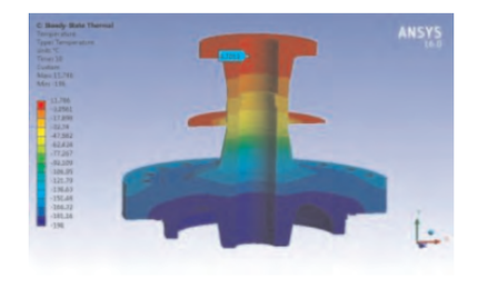
Figure 5 Temperature Field Distribution Cloud Diagram of Extended Bonnet
Table 2. Comparison of extended bonnet height requirements for NPS 16 cryogenic valves
|
Standard |
Height / mm |
|
JB/T 12621—2016 |
450 |
|
GB/T 24925—2018 |
450 |
|
MESC SPE 7T-200 |
450 |
|
BS 6364 |
250 |
|
MSS SP-134 |
700 |
Note: In MSS SP-134, the term “extended bonnet” refers to the distance from the valve centerline to the top of the stuffing box. When comparing height values specified in different standards, the measurements should be referenced to an equivalent datum point to ensure uniformity.
Based on the finite element analysis results (see Figure 1), at the strength test pressure of 37.5 MPa (1.5 PN), the stress in all pressure-bearing areas of the valve body remains within the allowable limits specified by the relevant standard. As shown in Figure 2, the strain at the middle flange gasket seal is negligible, and the stress in all areas remains within the allowable limits specified by the applicable standard. As shown in Figures 3 and 4, at the low operating temperature of −196 °C, the ball and valve seat achieve a proper fit under sealing pressure, the sealing pressure ratio is adequate, and the stress remains within the allowable limits specified by the standard. Figure 5 shows the distribution cloud diagram of the extended bonnet at −196 °C. The analyzed bonnet height is designed in accordance with MESC SPE 77-200, ensuring that the stuffing box temperature remains above 0 °C. This keeps the packing within its normal operating temperature range, ensuring sealing performance. It can therefore be concluded that the bonnet height is appropriate and the wall thickness sufficient to meet service conditions.
In developing this valve, a proprietary design approach was adopted to overcome technical challenges across multiple industries. Key inherent structural features were systematically optimized, overcoming traditional design limitations and mitigating potential technical risks.
The valve features a dual built-in seat configuration: one seat provides unidirectional sealing, and the other provides bidirectional sealing. This configuration enhances overall sealing performance and allows automatic pressure relief in the event of overpressure within the valve cavity. The pressure relief direction (inlet or outlet) can be customized based on actual operating conditions, ensuring safe operation. The valve seat’s structural design directly affects the overall performance of the valve. Ball valve seats have two primary leakage paths: the dynamic seal between the seat and the ball, and the static seal between the seat and the valve body’s inner bore. The dynamic seal first achieves an initial low-pressure seal through a preloaded spring within the seat, and subsequently utilizes the medium’s piston effect to establish a high-pressure seal. The static seal uses an energized seal ring that incorporates an internal spring. Because the energized seal ring requires extremely high dimensional accuracy and precision from the mating components, the valve seat in this region is specially designed. After optimization, the spring presses the seat against the ball, achieving a high-pressure seal through the action of the energized seal ring (Figure 6). In the pre-optimized design, variations in the valve seat structure caused the accumulator ring to shift by an amount A under medium pressure fluctuations, potentially compromising the sealing performance of the ring (Figure 7).
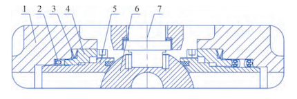
Figure 6. Optimized valve seat sealing structure
1. Valve bodies 2. Accumulator rings 3. Spring-loaded tabs 4. Spring-loaded tab seats 5. Valve seats 6. Balls 7. Valve stems
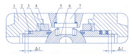
Figure 7. Pre-optimized valve seat sealing structure
1. Valve bodies 2. Accumulator rings 3. Spring-loaded tabs 4. Spring-loaded tab seats 5. Valve seats 6. Balls 7. Valve stems
The optimized valve design permits in-service repair and eliminates the ineffective—and potentially detrimental—gap A in the accumulator ring mounting groove, thereby significantly enhancing the valve’s sealing performance.
Double Block and Bleed (DBB) is a core feature of trunnion-mounted ball valves, with cavity bleed ports used during operation, maintenance, and performance testing of pipeline systems. Double Block and Bleed (DBB) is an essential feature of trunnion-mounted ball valves. Cavity bleed ports enable safe operation, maintenance, and performance testing in pipeline systems. In low-temperature pipeline applications, valves are typically enclosed in cold insulation, and bleed ports are generally fitted with sealed pipe threads. However, temperature fluctuations can gradually reduce thread preload and friction, potentially leading to bleed port thread failure in severe cases. The top-mounted bleed port configuration shown in Figure 8 greatly facilitates pipeline maintenance and inspection.
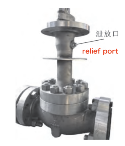
Figure 8: Top-mounted bleed port configuration
The energy storage ring is a critical element in the sealing system of cryogenic ball valves. Figure 9 illustrates the design before and after optimization. The optimized design adopts a composite structure consisting of a slotted metal ring and a PTFE lip. The lip is flanked by toothed grooves, creating a multi-stage sealing configuration. A double-layer spring support effectively compensates for valve body and seat shrinkage under cryogenic conditions, while maintaining a pressure-tight seal and minimizing the effects of microscopic surface irregularities on sealing performance.
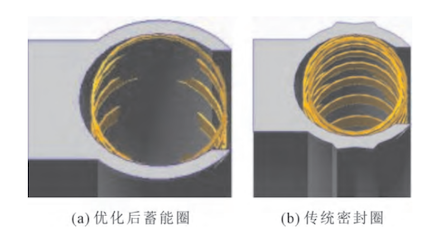
(a) Optimized energy storage ring (b) Conventional seal ring
Figure 9: Comparison of optimized and conventional seal rings
Low-temperature testing showed that the optimized energy storage ring reduced single-unit leakage to just one-fifth to one-tenth of that in the original valve design, demonstrating a substantial improvement in sealing performance.
In a ball valve, the valve stem is driven by an external actuator, which rotates the ball to achieve opening, closing, and shut-off functions. Under cryogenic operating conditions, rotation of the valve stem generates friction on the packing. Additionally, fluctuations in pressure and temperature can accelerate the aging of non-metallic packing materials. These factors can lead to valve stem packing leakage or even complete sealing failure. The optimized valve stem packing structure is shown in Figure 10.
The packing assembly shown in Figure 10 comprises an accumulator ring at the bottom, a V-shaped PTFE packing in the middle, and a low-leakage flexible graphite ring at the top. The accumulator ring acts as the primary seal, minimizing the risk of low-temperature media entering the subsequent sealing stage. The wear- and scratch-resistant V-shaped PTFE packing enhances overall service life. The low-leakage flexible graphite ring provides both reliable sealing and fire resistance.
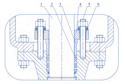
Figure 10: Optimized valve stem and packing structure
1. Valve stems 2. Combined packing 3. Packing gland 4. Packing plates 5. Fastener 6. Spring-loaded quantitative compression assembly
As shown in Figure 10, the combined packing attains its final sealing function by applying a preload through the fastener, spring, packing plate, and packing gland. The quantitative compression assembly regulates spring compression within the optimal range, providing a sustained elastic load and extending the service life of the disc spring. This sustained spring force ensures precise torque control and extends packing service life. The optimized packing seal structure complies with stringent international micro-leakage standards.
The required sealing surface pressure is defined as the minimum pressure per unit area on the sealing surface necessary to ensure a reliable seal. This requirement depends on factors including machining quality, dimensional accuracy, material properties, operating pressure, and temperature. The preload sealing surface pressure can be determined empirically using the following equation:

Where:
Qmf – Required sealing surface pressure (MPa)
k – Low-temperature coefficient, with values of 1.1 at −46 °C, 1.3 at −101 °C, and 1.6 at −196 °C
a and c are coefficients related to the sealing surface material (see Table 3 13 in the Practical Valve Design Manual).
P – Fluid operating pressure (MPa)
b – Sealing surface width (mm)
Because sealing surface materials tend to become brittle at low temperatures and the fit between sealing elements is reduced, NPS 4 Class 300 tooling ball valves were selected for comparative testing of sealing performance at various temperatures. The results indicate that the measured required sealing surface pressures generally align with the calculated values above.
An NPS 4 Class 300 tooling ball valve was selected for testing. After multiple life-cycle tests, the measured seat leakage increased significantly. The seat seal in the tested valve was made of PCTFE. Upon disassembly and inspection, the sealing surface exhibited varying degrees of damage. A comparative analysis was performed between domestically produced and imported PCTFE sealing rings. The physical properties and life-test results for both brands are presented in Table 3 and Figure 11.
Table 3: Comparison of PCTFE Sealing Ring Material Parameters
|
Product Performance |
Domestic |
Imported |
|
Density (g/cm³) |
2.10 |
2.10–2.16 |
|
Water Absorption (%) |
0.005 |
≤0.01 |
|
Operating Temperature (°C) |
−193 to +150 |
−200 to +150 |
|
Tensile Strength (MPa) |
35–45 |
31–45 |
|
Elongation (%) |
50–140 |
50–150 |
|
Shore Hardness (D) |
80–90 |
70–80 |
|
Dielectric Constant |
2.2–2.7 |
2.3 |
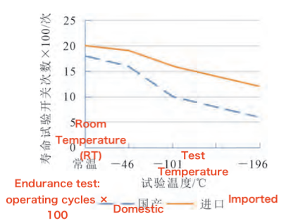
Figure 11: Valve Sealing Ring Performance and Service Life Test
Although the two brands of sealing rings differed in performance and service life, the data in Table 3 indicate that their physical properties are largely similar. Therefore, it is recommended that domestic valve manufacturers strengthen fundamental research and gather extensive experimental data to better understand the relationship between sealing ring material properties and service life.
This paper presents the simulation analysis and structural optimization of a large-diameter, low-temperature, top-entry trunnion-mounted ball valve. The study examines the key factors influencing the design of cryogenic ball valves and, for the first time, proposes the selection of the low-temperature coefficient k for calculating the sealing surface pressure under cryogenic operating conditions. In summary, long-term reliability, stable performance, and operational safety are the key quality indicators for evaluating large-diameter, low-temperature, top-entry ball valves. It is crucial to address and optimize design challenges at the source, while integrating advanced cryogenic valve technologies imported from abroad with design methods that incorporate independent intellectual property rights. This approach provides a solid foundation for the full domestication of large-diameter, high-pressure, low-temperature, top-entry ball valves.