Abstract
High-temperature valves generally require heat-resistant materials, which are both costly and limited in service life. This design integrates cooling structures not only in the three-way flow channels and valve body cavity but also in the ball and stem. By reducing the operating temperature of the valve body and internal components, the system lowers material costs and extends the service life of the sealing surfaces, thereby enhancing equipment reliability and ensuring environmental safety. The heat absorption of the cooling water and flow-channel steel is calculated, and finite element simulation is performed to analyze the internal temperature field of the ball valve. These measures greatly enhance the design’s reliability, delivering a high-quality and dependable product to users.
In a petrochemical new energy system, a T-shaped three-way ball valve is required, designed to operate at 785 °C with a nominal pressure of Class 300 and a nominal diameter of DN200. The valve handles an ultra-high-temperature gas containing granular catalysts, with the sealing surface hardfaced using STL carbide. Its body features three channels—one inlet and two outlets—operating in three modes: straight-through, side-through, and closed, and is actuated electrically or pneumatically. The cooling system is divided into two subsystems, the first of which is dedicated to cooling the ball and stem. Because these components are housed within the valve body and must rotate, this subsystem involves numerous components and features a complex structure. The purpose of the cooling system is to reduce the temperature of key components. This decreases the heat resistance requirements for valve materials, thereby lowering material costs. The purpose of the cooling system is to lower the temperature of key components, which reduces the heat-resistance requirements for valve materials and, consequently, decreases material costs. Additionally, reducing component temperatures extends the service life of the sealing surfaces, enhances operational safety, and ensures reliable performance of both electric and pneumatic actuators. This article presents the design of the cooling system, calculates its cooling effectiveness, and provides finite element simulations of the valve body cavity, collectively enhancing product design quality and installation reliability while earning strong recognition from end users.
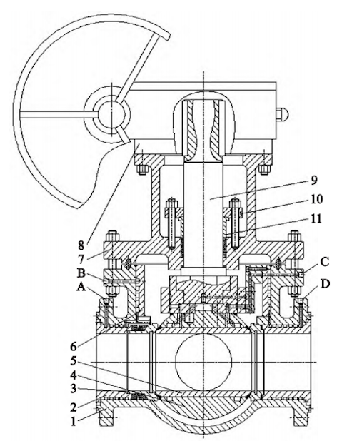
A. Inlet-End Water Inlet
B. Middle Cavity Outlet
C. Stem Water Inlet
D. Outlet-End Water Inlet
1. Valve Body 2. Inlet Cooling Sleeve 3. Inlet Seat 4. Outer Ball Sleeve
5. Inner Ball Sleeve 6. Middle Cavity Cooling Sleeve 7. Bonnet 8. Electric Actuator
Figure 1: General assembly diagram
The ball is a critical valve component, and its cooling has a decisive impact on service life. To facilitate cooling, the ball is divided into two parts: an inner sleeve and an outer sleeve. Cooling grooves are machined at both ends of the outer sleeve before the two parts are assembled, welded, and precision-finished. The ball rotates via the valve stem, with its upper end welded to the stem seat to form a single, integrated unit. The internal hexagonal profile of the stem seat engages with the external hexagonal profile at the stem’s lower end, ensuring that the ball and stem move synchronously (Figure 2). Ball cooling water enters the valve body via the center flange, flows through the central cooling sleeve, the guide tube holder, and the clamp, and then reaches the stem seat. Since the stem seat rotates, a flow channel is machined into its outer diameter to direct water into the inner section and then into the ball’s cooling grooves, as illustrated in Figures 2–7. The inlet flow channels are labeled A1 through A10, and the outlet flow channel is designated B1.
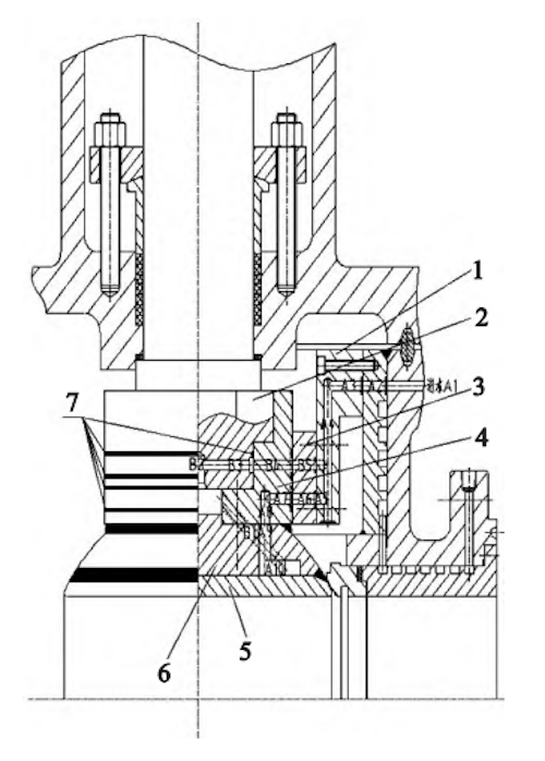
1. Conduit Frame 2. Stem Hex Head 3. Clamp Ring 4. Stem Seat 5. Inner Ball Sleeve 6. Outer Ball Sleeve 7. O-Ring
Figure 2. Ball and stem cooling paths
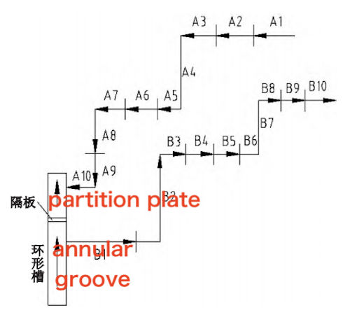
Figure 3. Ball and stem cooling ways
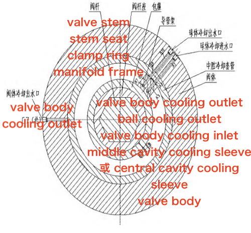
Figure 4. Cross-sectional view of the inlet and outlet water paths in the valve body center flange
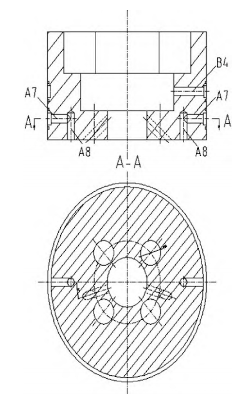
Figure 5 Stem seat
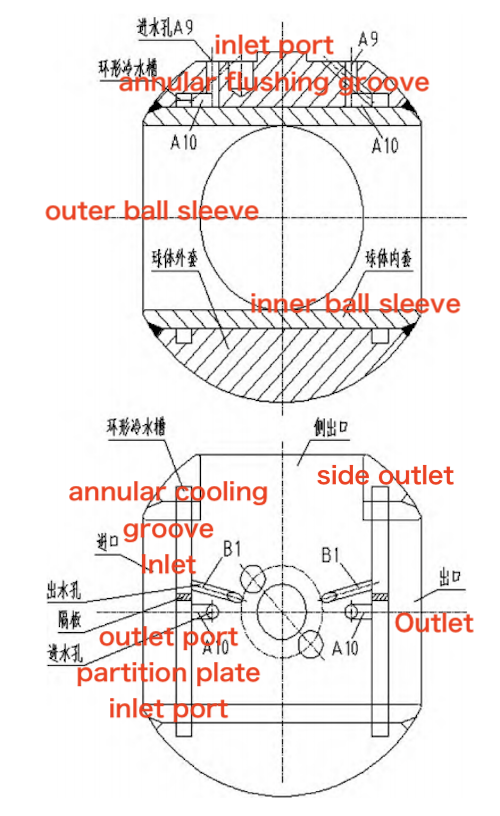
Figure 6. Cross-sectional view of the ball
All three flow paths and the central cavity of the three-way ball valve carry high-temperature media, making effective cooling essential. In this design, cooling water enters each flow path through inlets on the outer diameter of the corresponding end flange, with each flow path fitted with a dedicated cooling jacket. The outer diameter of each cooling jacket is machined with a square-threaded annular groove that functions as the cooling channel. Water then flows through the spiral groove of the center cavity jacket into an upper annular groove and exits via the center flange outlet (Figures 8–12). The cooling jackets and valve seat structures vary among the three flow paths. Two disc springs are installed on the inlet valve seat to provide preload, and both thermal insulation and sealing structures are incorporated. The front and rear ends of the side-outlet cooling sleeve are welded to the valve body to prevent water leakage. Because the valve seat must maintain sealing preload, a compression sleeve and a threaded adjustment sleeve are installed at the rear of the valve seat, and a retaining pin is placed on the outer circumference to prevent vibration or misalignment (Figure 11). For the center cavity cooling sleeve, the upper and lower end faces are welded to the valve body. Three flow ports are machined at its lower end: C1 (4), C2 (3), and C3 (3). These ports converge into the main flow port, C5, as shown in Figures 8 and 9. Additionally, two transverse holes, A2 and B9, are drilled at the upper end of the sleeve. Externally, these holes connect to the valve body’s water inlet A1 and outlet B10, while internally, they connect respectively to A3 and B8 on the guide frame. During assembly, two threaded holes must also be machined to secure the guide frame (Figure 7).
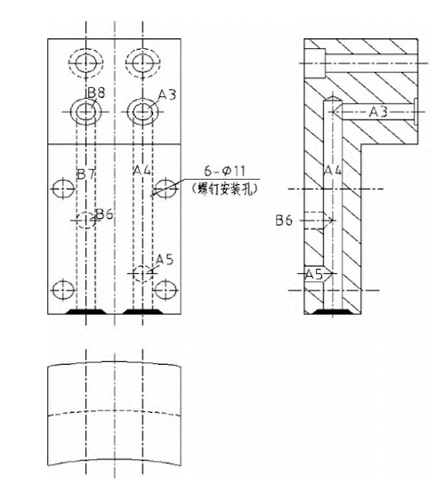
Figure 7. Flow channel structure of the cooling jacket
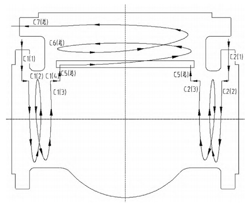
Figure 8. Cooling route of the valve body cavity and inlet/outlet flow channels
C1. Inlet flange and flow channel
C2. Outlet flange and flow channel
C3. Side flange and flow channel
C5 (total). Merged inlet flow channels at the lower end of the valve body cavity
C6 (total), C7 (total). Spiral annular flow channels in the valve body cavity leading to the center flange outlet
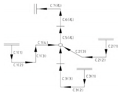
Figure 9. Valve body inlet, outlet, and side flow channels with cooling routes in the cavity
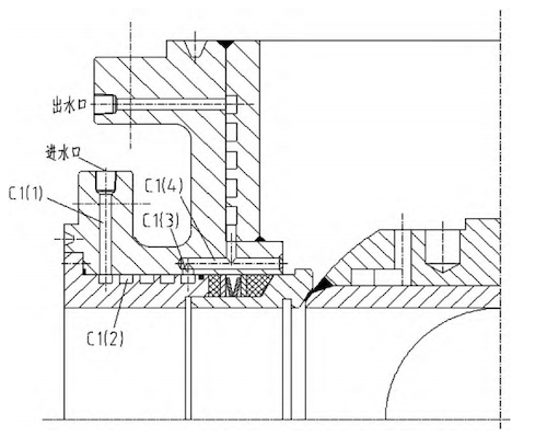
Figure 10. Cross-sectional view of the valve body cavity and inlet
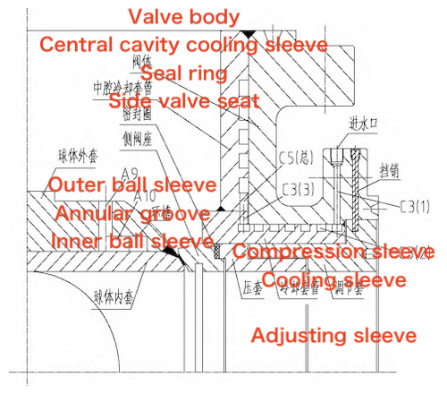
Figure 11. Cross-sectional view of the valve body and lateral outlet
(1) Calculation of cooling water for the valve body and the inlet, outlet, and side flow channels:

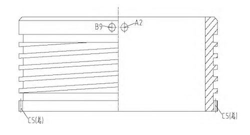
Figure 12. Half-sectional view of the cooling sleeve in the valve body cavity
The total flow rate for the three inlets is:

The total flow rate for the single outlet of the valve body is also 95.4 L/min.
(2) Cooling Water Calculation for the Ball and the Lower End of the Valve Stem
The cooling water flow rate for the ball and the lower end of the valve stem is calculated as:

(3) Mass of Steel Components
Mass of the valve body: 962 kg
Mass of the ball and load-bearing stem: 242 kg
(4) Heat Absorption Calculations
① Heat absorption of water in the shell and flow channels:

② Heat absorption of water in the ball and stem

Fluent was used to simulate and analyze the temperature and velocity distributions within the valve cavity. The measured inlet temperature was approximately 75 °C, and the inlet velocity was 4.2 m/s. The medium consisted of turbulent, high-temperature air with a high Reynolds number. The k-ε model was applied, turbulence intensity was set to 5%, and the energy equation was enabled to perform a coupled thermal-fluid simulation. The wall heat transfer coefficient was determined from the preliminary calculations, and the mesh was generated using the tetrahedral method. Because of significant variations within the valve cavity and boundary regions, local mesh refinement was applied, yielding a final grid of approximately 300,000 elements. Mesh quality parameters—including aspect ratio, skewness, and orthogonality—met all criteria for accurate simulation. The temperature field in the straight-through state is shown in Figure 13, with the outlet temperature approximately 32 °C lower than the inlet and the temperature within the valve cavity. Based on the cavity velocity distribution, the wall heat transfer coefficient was determined. The velocity trace distribution (Figure 14) reveals a distinct heat exchange boundary layer along the valve cavity wall, where heat transfer efficiency is significantly higher. Since the side-pass outlet is closed in this state, the local flow near the outlet is weak, generating turbulence and numerous eddies within the valve cavity. This causes partial backflow, increasing the complexity of the outlet flow field. Overall, the heightened turbulence improves heat exchange between the cavity wall and the high-temperature gas. In the straight-through state, most of the gas bypasses the side-pass outlet and flows directly from the inlet to the outlet, resulting in only a minor velocity difference between them.
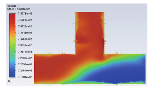
Figure 13. Temperature field (straight-through)
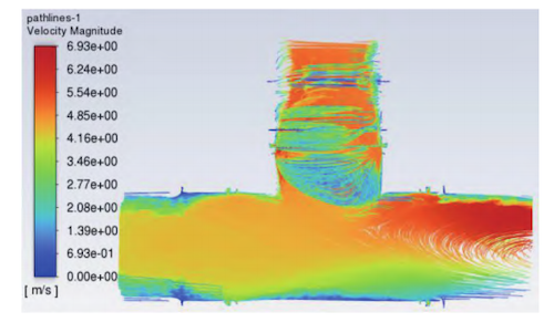
Figure 14. Velocity traces (straight-through)
The temperature field in the side-pass state is shown in Figure 15. Combined with the velocity trace distribution at the side-pass outlet (Figure 16), it is evident that the straight-through state provides slightly better cooling performance. This is primarily because closing the straight-through port directs most of the hot inlet gas toward the side-pass outlet, which cannot discharge it promptly. As a result, local heat transfer efficiency is reduced, leading to some heat accumulation.
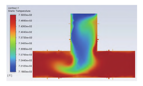
Figure 15. Temperature Field (Side-Pass)
The cooling system for the high-temperature three-way ball valve was developed through close collaboration among industry, academia, and research institutions. Following rigorous design and repeated optimization, an integrated cooling system was implemented for the ball and stem, the inlet and outlet flow channels, and the central cavity. The design incorporates several key innovations, including a square-threaded cooling structure machined into the outer surface of the flow channel sleeve. A ball featuring a dedicated downstream cooling structure with an annular groove between the inner and outer sleeves; and a stem seat installed within the stem cooling hole, surrounded by an annular clamp. Cooling water passes from the clamp into a guide tube, supplying each inlet and outlet channel through ten dedicated cooling pipes. This configuration showcases both technical ingenuity and robust performance, effectively reducing component temperatures, lowering material costs, extending service life, and ensuring a reliable foundation for safe, long-term operation.
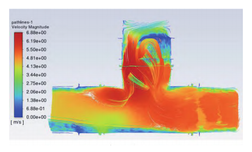
Figure 16. Velocity traces (side-pass)