Using the general finite element analysis software ABAQUS, a thermal simulation was conducted on the welding process of the connection flange of a company's X80 steel fully welded ball valve. Based on the simulation results, an optimized welding process plan was proposed to address and improve existing welding issues in the connection flange of the fully welded ball valve.
Oil and gas pipelines are the most economical, safest, and most efficient means of long-distance oil and gas transportation. They are widely used across China for this purpose. Ball valves, known for their low fluid resistance, simple structure, reliable sealing, and fast operation, are commonly employed in oil pipelines to stop the flow, regulate distribution, and redirect the medium. The fully welded ball valve produced by the company requires high airtightness and a service life of over 30 years, making precise control of welding deformation critical. The current production process employs manual arc welding for root passes and submerged arc welding for fill passes. However, this method results in significant weld seam deformation, which not only necessitates reserving machining allowances prior to welding but also substantially increases the labor time required for subsequent processing steps.
Optimizing the welding method and process to minimize deformation is therefore a pressing issue. In this study, the effects of temperature-dependent material properties on the thermal field were fully considered. ABAQUS software was used to simulate the temperature field during welding of the fully welded ball valve. The simulation results closely reflect the actual welding conditions of the solid workpiece and enable a comprehensive thermal stress analysis of the model.
- After welding, the valve body must remain free from deformation.
- The weld seam must exhibit good toughness and minimal deformation. The groove should be designed appropriately, with a suitable welding method and seam location selected.
- The heated area during welding must not be too large, and the temperature must be properly controlled to avoid damaging the sealing components inside the valve body.
- Residual stresses generated at the weld after welding must be addressed with appropriate stress-relief measures.
- Weld beads must not form. The weld metal surface should not be lower than the base material, and the weld reinforcement should not be excessively high.
This study focuses on a large-diameter fully welded ball valve. The assembly process of the ball valve involves first assembling the internal components, followed by integrating the left and right sections with the central body. After welding, the ball must operate smoothly, remain user-friendly, and ensure reliable sealing. To optimize computational efficiency, the welded section of the ball valve is simplified for modeling purposes, while parts of the valve body that have minimal influence on the weld are omitted. A segment on both sides of the weld is selected for modeling, as shown in Figure 1. The model’s boundary conditions allow for free heat conduction from the inner to the outer regions, consistent with the characteristics of pipeline steel. The welding model is meshed using a non-uniform hexahedral grid, with refinement applied to the weld zone. The innermost annular portion of the valve body and the contact plane between the sealing rings are of particular focus, as minimizing post-weld deformation in these areas is the primary objective of this process optimization.
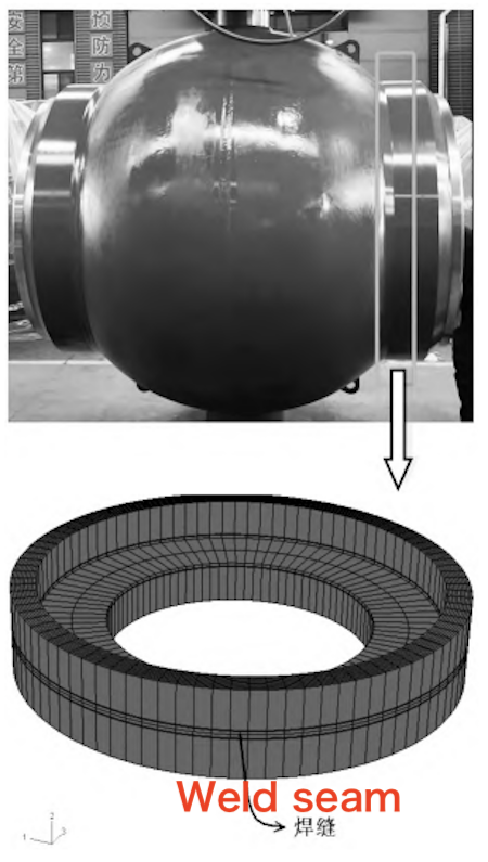
Figure 1: Welding model of the ball valve
The material used in the model is X80 steel, with its main chemical composition listed in Table 1.
Table 1. Chemical Composition of X80 Steel (Mass Fraction, %)
|
Element |
C |
Si |
Ni |
Mn |
P |
S |
Cu |
|
% |
0.052 |
0.23 |
1.50 |
0.008 |
0.002 |
0.15 |
0.29 |
The main properties of X80 steel are listed in Table 2, including elastic modulus, thermal expansion coefficient, yield stress, and strain hardening modulus at various temperatures.
The weld features a U-shaped groove, a butt gap of 0.5 mm, and a single-sided blunt edge thickness of 1 mm.
|
Temperature (°C) |
Elastic Modulus (GPa) |
Thermal Expansion Coefficient (×10⁻⁶/°C) |
Yield Stress (MPa) |
Strain Hardening Modulus (GPa) |
|
20 |
210.00 |
12.3 |
556 |
21.000 |
|
200 |
195.00 |
12.3 |
490 |
19.500 |
|
400 |
172.00 |
12.3 |
438 |
17.200 |
|
600 |
155.00 |
12.3 |
280 |
15.500 |
|
800 |
116.00 |
12.3 |
80 |
11.600 |
|
1000 |
45.00 |
12.3 |
30 |
4.500 |
|
1100 |
11.00 |
12.3 |
18 |
1.100 |
|
1200 |
1.00 |
12.3 |
10 |
0.100 |
|
1300 |
0.05 |
12.3 |
– |
0.005 |
|
1500 |
0.05 |
12.3 |
– |
0.005 |
Note: Yield stress values at 1300°C and 1500°C are not specified.
|
Welding Type |
Welding Method |
Electrode Diameter (mm) |
Welding Speed (m/min) |
Current (A) |
Voltage (V) |
|
Root Pass Welding |
Manual Arc Welding |
3.2 |
0.25 |
80–100 |
23–24 |
|
Fill and Cap Welding |
Submerged Arc Welding |
4.0 |
0.90 |
700 |
33 |
The original welding process uses manual arc welding for the root pass, with electrode model E8010 and a diameter of 3.2 mm. Submerged arc welding is employed for the fill and cap passes, using a wire diameter of 4 mm. The welding process parameters are presented in Table 3.
After the ball valve is secured by spot welding, the roundness runout of its sealing ring mating surface is measured and recorded as a reference for post-weld deformation. Following the root welding, the roundness runout is measured again, and the difference from the reference value is used to determine the deformation caused by the root pass. After the entire welding process is completed, the valve is cooled at room temperature for 24 hours, and the roundness runout is measured again to assess the final post-weld deformation. A total of seven ball valves were welded and tested. The results are shown in Table 4. The average deformation after the root pass was 0.68 mm, and the average final deformation after welding was 2.95 mm.
Table 4. Post-Welding Deformation (mm)
|
Welding Stage |
Sample 1 |
Sample 2 |
Sample 3 |
Sample 4 |
Sample 5 |
Sample 6 |
Sample 7 |
Average (mm) |
|
Base Weld |
0.65 |
0.59 |
0.72 |
0.68 |
0.64 |
0.75 |
0.70 |
0.68 |
|
Fill Weld |
2.89 |
2.77 |
3.08 |
2.96 |
2.94 |
3.05 |
2.97 |
2.95 |
The original welding process employs manual arc welding for the base weld. This method is easy to operate, flexible in application, effective in dispersing stress and controlling deformation, and provides good welding quality. Based on the welding parameters, the thermal deformation was calculated, and the results are shown in Figure 2. It is evident that the area with the greatest thermal deformation is the plane where the valve body contacts the sealing ring, with a maximum deformation of 0.56 mm. This value is slightly lower than the experimental deformation result for the base weld. The primary reason for this discrepancy is the variability in welding parameters during the experiment, largely caused by differences in welding technique among operators.
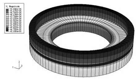
Figure 2. Thermal deformation after base welding
Using the parameters for the fill welding process, the post-welding deformation of the ball valve was calculated. The thermal deformation is illustrated in Figure 3, showing that the deformation of the sealing surface reaches 2.73 mm. This calculated value is slightly less than the experimental result. Figure 4 provides a comparison of the mesh structure before and after deformation, magnified tenfold. The gray mesh represents the structure before deformation, while the black mesh indicates the structure after deformation. It is clear that both local and overall deformations are significant after welding.
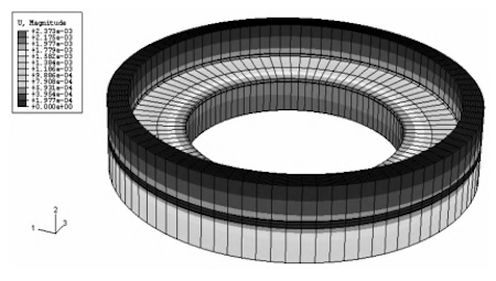
Figure 3. Thermal deformation after fill welding
Based on the simulation of thermal deformation in the ball valve, the primary causes of deformation are preliminarily identified as follows:
- The heat input (also referred to as line energy) during the base welding process using manual arc welding is excessively high.
- Inconsistent welding techniques resulting from operator variability contribute to instability in the welding quality.
- The initial deformation caused by the excessive heat input and unstable manual welding further intensifies the deformation that occurs during subsequent submerged arc welding.
- Thermal deformation is further exacerbated by stress concentration during the submerged arc welding process.
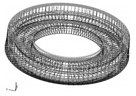
Figure 4. Comparison of mesh deformation before and after welding (magnified 10×)
Based on the above simulation analysis, it is proposed to adopt laser welding for the base welding, using a fiber laser. A U-shaped groove will be used, with a butt gap of 0–0.1 mm and a blunt edge thickness of less than 1 mm. The filling weld will follow the original submerged arc welding process, and a segmented reverse welding sequence will be applied.
Given that thermal deformation during base welding significantly affects the deformation behavior of subsequent submerged arc welding, manual welding is not recommended. Instead, automated welding with relatively low line energy is advised. Laser welding is recommended for the base layer due to its advantages, including high welding speed, a narrow heat-affected zone, minimal thermal deformation, and a high degree of automation. Utilizing laser welding for bottom sealing can effectively minimize thermal deformation during the base welding stage. Table 5 presents the laser welding process parameters.
Table 5. Laser Welding Process Parameters
|
Melt Welding Form |
Welding Method |
Laser Power (kW) |
Welding Speed (m/min) |
Defocus Amount (mm) |
Offset Amount (mm) |
|
Base Welding |
Laser Welding |
3.0 |
5.0 |
-1 |
0 |
The filling weld follows the original welding process; however, a segmented reverse welding sequence is adopted. This technique helps to distribute the heat input more evenly and effectively reduces thermal deformation during welding. The circumferential weld is divided into seven sections, which are welded in reverse order, as illustrated in Figure 5. Submerged arc automatic welding is the preferred method due to its cost-effectiveness. Since the groove gap resulting from laser welding is narrower than that of manual arc welding, the process parameters for submerged arc welding are also slightly lower than those in the original process. Table 6 presents the welding process parameters for the filling weld.
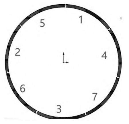
Figure 5 Segmentation of girth weld
Table 6. Filling Welding Process Parameters
|
Welding Type |
Welding Method |
Welding Diameter (mm/s) |
Welding Current (A) |
Arc Voltage (V) |
Wire Feed Speed (m/min) |
|
Filling Cap Welding |
Submerged Arc Welding |
4.0 |
650 |
32 |
0.9 |
Based on the proposed process, a welding heat simulation calculation plan was developed. Figure 6 shows the results of the thermal deformation from laser backing welding. The thermal deformation in the sealing area is only 0.12 mm, which is significantly lower than that observed in manual arc welding. In addition to the concentrated energy and low heat input characteristic of laser welding, the high stability of automated laser welding also contributes to the reduced thermal deformation.
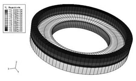
Figure 6 Thermal deformation of laser root welding
A thermal simulation model was established based on the submerged arc welding process to calculate the resulting thermal stress. The results are shown in Figure 7. The deformation in the sealing area is 1.57 mm, which is less than that produced by the original welding process. Figure 8 presents a comparison of the mesh deformation before and after segmented reverse welding, magnified by a factor of 10. It is clear that the overall deformation is also smaller than that of the original process.
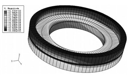
Figure 7 Thermal deformation of segmented reverse welding
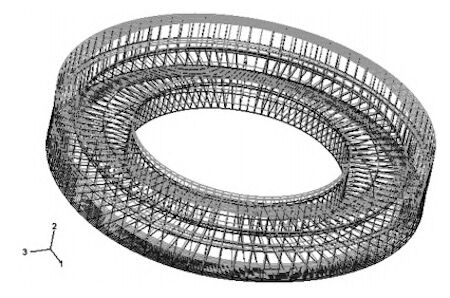
Figure 8 Comparison of mesh deformation after segmented reverse welding (10×)
Welding verification was conducted using the improved welding process. The verification method is described in Section 3. The results are presented in Table 7. The average deformation after backing welding was 0.122 mm, and the average deformation after filling was 1.635 mm. Sample 4 in Table 7 exhibited weld penetration during laser welding and failed to weld successfully. This failure was attributed to poor groove machining accuracy, specifically excessive butt gaps in certain areas where the joint was flared, which caused the laser beam to pass through the gap without forming an effective butt weld. Overall, the welding deformation produced by the improved process was smaller than that of the original welding method.
Table 7. Deformation of Base Welding and Filling Welding (mm)
|
Welding Type |
Sample 1 |
Sample 2 |
Sample 3 |
Sample 4 |
Sample 5 |
Sample 6 |
Sample 7 |
Average |
|
Base Welding |
0.14 |
0.13 |
0.10 |
Unsuccessful |
0.11 |
0.13 |
0.12 |
0.122 |
|
Filling Welding |
1.68 |
1.59 |
1.59 |
Unsuccessful |
1.63 |
1.70 |
1.62 |
1.635 |
- Simulation analysis shows that laser base sealing combined with segmented reverse arc filling welding can effectively reduce thermal deformation compared to the original welding process for coal connections.
- Laser welding requires high precision in groove preparation, and successful welding depends on accurate assembly.
- Using welding simulation to guide process optimization can conserve welding materials and serves as an effective method for parameter refinement.
- Upon completion of welding, pressure testing confirmed that there was no leakage at the weld, and the sealing surface met all technical requirements.
- X-ray inspection revealed no internal defects such as porosity, slag inclusions, lack of fusion, or cracks in the coal seam weld, indicating full compliance with technical standards.