Leakage in pipelines transporting toxic or flammable gases can easily lead to fires, explosions, and other serious accidents. Large-diameter ball valves are widely used in mine ventilation and natural gas pipelines, where sealing performance is a critical safety factor. This study investigates the bidirectional (forward and reverse) sealing performance of a 40-inch fully welded ball valve under both high-pressure and low-pressure conditions. The results indicate that in both forward and reverse sealing, the valve seat support ring is a high-stress region; however, the maximum equivalent stress remains below the material’s yield strength. The areas of highest stress and maximum deformation in the valve seat seal ring are concentrated at the two sharp corners in contact with the support ring. Under high-pressure conditions, the contact pressure between the valve seat and the ball exceeds the internal medium pressure, thus meeting sealing requirements. Under low-pressure conditions, however, the contact area is significantly reduced, and the operating pressure must not fall below the design pressure to avoid a decline in sealing performance. This research provides valuable insight for defining the appropriate sealing pressure range and for performing bidirectional sealing analysis of large-diameter ball valves.
Fully welded ball valves are extensively used in gas transmission pipelines due to their advantages, including zero external leakage, resistance to high temperatures and pressures, corrosion resistance, lightweight construction, and ease of installation. However, under the combined effects of temperature, pressure, and corrosion, the contact area between the valve seat and the ball is susceptible to sealing failure. Because the internal sealing components of a fully welded ball valve are non-replaceable, and the rubber sealing ring must endure high-temperature welding, a failure of the seal typically renders the entire valve unusable. Therefore, analyzing the sealing performance under various operating conditions is essential for the proper design and reliable application of ball valves.
Shuxun Li et al. designed the sealing structure of a fully welded ball valve for long-distance natural gas pipelines and proposed three solutions: a double piston effect valve seat, double seals, and emergency rescue mechanisms. Jiping Lei et al. analyzed a new type of bidirectional metal-seated rotary ball valve using ANSYS and verified its zero-leakage performance. Han Xiao et al. developed an integral bidirectional sealed valve seat ball valve suitable for oil and natural gas pipelines. Qing Li et al. employed finite element simulation to study the sealing pressure ratio and deformation of deep-sea ball valve seats. Weisha Hao et al. analyzed the failure factors of ultra-low temperature liquefied natural gas ball valves to provide references for future designs. Yefei Wu et al. examined the sealing performance of liquefied natural gas ball valves and proposed low-temperature sealing design recommendations. Awad et al. simulated pressure fluctuations in sealing systems using MATLAB to determine optimal stable operating conditions. Peng et al. established a leakage model under varying pressures incorporating plastic deformation effects and validated it through experiments.
Most existing studies focus on valve seat structure design and system stability, with few analyses addressing sealing performance and mechanical properties under both high and low pressure conditions. To fill this gap, this paper investigates the sealing performance of a 40-inch fully welded ball valve at 17.1 MPa (high pressure) and 0.6 MPa (low pressure), analyzing equivalent stress, contact pressure, and deformation distribution during forward and reverse sealing.
The 40-inch large-diameter ball valve is suitable for DN1000 natural gas long-distance pipelines or station control. The valve body and ball are made from A350 low-temperature steel forgings. Since it is a welded structure, the sealing assembly cannot be replaced after welding, making the performance of the sealing structure particularly critical. The ball valve sealing assembly consists of a ball, a valve seat, a protective pad, and a valve seat support ring. The valve seat provides the sealing function, while the protective pad offers buffer protection for the valve seat. The structure of the ball valve sealing component is relatively complex, with all components being axisymmetric. To save computation time and improve accuracy, this paper analyzes only a two-dimensional model of the sealing component, as shown in Figures 1 and 2.
During the ball valve sealing process, when there is fluid pressure in the flow channel and no pressure in the middle cavity, the valve performs forward sealing. Conversely, when there is no fluid pressure in the flow channel and pressure exists in the middle cavity, the valve performs reverse sealing. According to sealing theory and the principle of force balance, successful sealing depends on the contact pressure between the valve seat sealing ring and the ball relative to the medium pressure. If the contact pressure in any area of the sealing surface exceeds the medium pressure, sealing is achieved; otherwise, it is not.
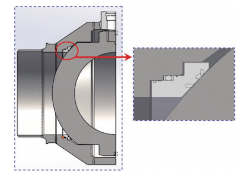
Figure 1 Geometric structure of fully welded ball valve
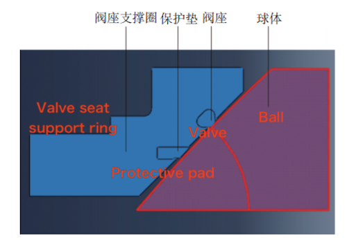
Figure 2 Contact pair of ball valve sealing components
The following assumptions were made prior to the study:
- The material has defined elastic modulus and Poisson’s ratio.
- The tensile and compressive creep properties of the material are identical.
- Creep does not cause any volume change.
- The effects of medium pressure and temperature variations on the sealing ring are neglected.
The valve seat sealing ring is made of hydrogenated nitrile rubber (HNBR), and the protective pad is made of nylon. The Mooney-Rivlin model effectively describes the deformation behavior of rubber materials up to 150% strain and remains stable within small deformation ranges. Since the compression of the ball valve is less than 150%, the Mooney-Rivlin model is employed to characterize the mechanical properties of the valve seat and protective pad. The strain energy density function is expressed as:
W=C10(I1−3)+C01(I2−3)
where:
W is the strain potential energy.
C10 are material coefficients in the Mooney-Rivlin model.
I1 and I2 are the first and second invariants of the strain tensor.
The stress-strain relationship can be expressed accordingly.
The density of the valve seat is 1200 kg/m³, and the density of the protective pad is 1150 kg/m³. The coefficients C10 and C01 are 2.79 MPa and 0.7 MPa, respectively. The material parameters of the ball and valve seat support ring are shown in Table 1.
Since the contact sealing analysis of the ball valve involves rubber and complex contact conditions, four-node elements are used for mesh generation, with local refinement in the contact areas. The mesh contains 5,015 elements for the sphere and the valve seat support ring, and 2,811 elements for the valve seat sealing ring and the protective pad. As the valve seat support ring and the valve seat are axisymmetric about the pipeline axis, they are simplified into axisymmetric plane models. The penalty method is used to simulate surface contact, and four contact pairs are defined:
- between the valve seat sealing ring and the valve seat support ring
- between the protective pad and the valve seat support ring
- between the valve seat sealing ring and the sphere
- and between the protective pad and the sphere
The initial friction coefficient is set to 0.2. Loads and boundary conditions are applied as shown in Figure 3.
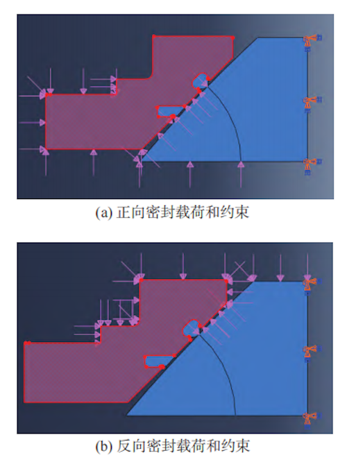
(a) Forward sealing: load and constraint (b) Reverse sealing: load and constraint
Figure 3 Finite element model of the ball valve sealing assembly
Table 1 Material Parameters of the Ball and Seat Support Ring
|
Part |
Elastic Modulus E (GPa) |
Shear Modulus G (GPa) |
Poisson's Ratio |
Density ρ (kg/m³) |
Tensile Strength σₜ (MPa) |
Minimum Yield Strength σᵧ (MPa) |
|
Ball |
202 |
77.7 |
0.3 |
7750 |
485–655 |
250 |
|
Seat Support Ring |
202 |
77.7 |
0.3 |
7750 |
515–690 |
415 |
Figure 4 shows the equivalent stress distribution (stress cloud diagrams) of the sealing assembly of the fully welded ball valve under both high-pressure and low-pressure conditions. The following observations can be made:
Under the high-pressure sealing condition of 17.1 MPa, during forward sealing, the highest stress concentration occurs at the upper-right contact corner between the valve seat seal ring and the valve seat support ring, reaching approximately 211 MPa. During reverse sealing, the highest stress also occurs on the valve seat support ring, this time at the lower-left contact corner, and similarly reaches 211 MPa. Although the equivalent stress under reverse sealing is slightly higher than that under forward sealing, it remains well below the yield strength of the seat support ring (415 MPa), indicating no plastic deformation occurs.
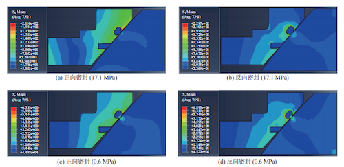
(a) Forward seal (17.1 MPa) (b) Reverse seal (17.1 MPa) (c) Forward seal (0.6 MPa) (d) Reverse seal (0.6 MPa)
Figure 4 Equivalent stress cloud diagram of ball valve seal assembly
Under the low-pressure sealing condition of 0.6 MPa, during forward sealing, the maximum stress on the valve seat support ring is about 6.5 MPa at the upper-right contact corner. In reverse sealing, the highest stress occurs at the left arc of the valve seat seal ring and reaches approximately 229 MPa; another high-stress point of about 6.9 MPa is observed at the lower arc contact corner. Under both high- and low-pressure sealing conditions, all equivalent stress values are below the yield strength of the valve seat support ring, ensuring that no yield deformation occurs.
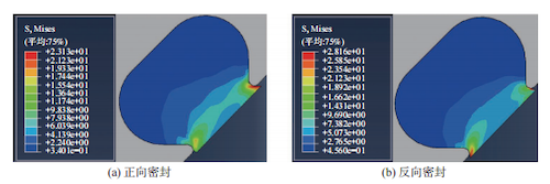
Figure 5 presents the equivalent stress distribution of the valve seat seal ring under high-pressure conditions (17.1 MPa) for both forward and reverse sealing. As shown, during contact sealing in both directions, the lower end of the seal ring is compressed by the ball, resulting in high-stress regions at the two sharp corners where the seal ring contacts the valve seat support ring.
In forward sealing, the stress concentration is greater at the upper-right corner, where the maximum von Mises stress reaches approximately 23 MPa. In reverse sealing, both corners exhibit high stress, with the peak stress reaching around 28.2 MPa. To improve the stress distribution and reduce stress concentration on the sealing ring, it is recommended to increase the chamfer radius of the sharp contact corners on the valve seat support ring from 0.5 mm to 1 mm. This modification reduces the maximum stress by approximately 15%, thereby helping to extend the service life of the sealing ring.
(a) Forward sealing (b) Reverse sealing
Figure 5 Equivalent stress cloud diagram of the valve seat sealing ring under 17.1 MPa high-pressure sealing conditions
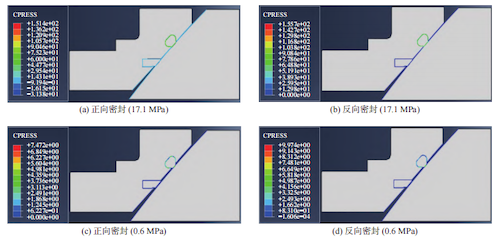
Figure 6 presents the contact pressure distribution of the sealing components of the fully welded ball valve under both high-pressure and low-pressure sealing conditions. At the high-pressure condition of 17.1 MPa, the maximum contact pressures during both forward and reverse sealing occur at the sharp interface between the upper right edge of the valve seat sealing ring and the valve seat support ring, reaching approximately 151 MPa and 155 MPa, respectively. The contact pressure between the valve seat sealing ring and the ball is relatively high and exceeds the medium pressure of 17.1 MPa, thereby serving as the primary sealing interface. In contrast, the contact stress between the protective pad and the ball is comparatively low, indicating that the pad acts as a buffer to protect the sealing ring. Under the low-pressure condition of 0.6 MPa, the contact pressure between the valve seat sealing ring and the ball remains greater than the medium pressure during both forward and reverse sealing, ensuring effective sealing. At this pressure level, the protective pad has not yet come into contact with the ball.
(a) Forward seal (17.1 MPa) (c) Forward seal (0.6 MPa) (b) Reverse seal (17.1 MPa) (d) Reverse seal (0.6 MPa)
Figure 6 Contact pressure of ball valve seal assembly
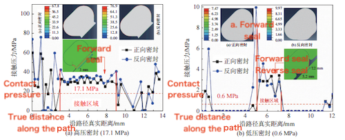
During operation, the contact pressure between the valve seat sealing ring, which serves as the main sealing element, and the ball is a critical indicator of the valve’s sealing performance. Therefore, a quantitative analysis of this pressure is essential. As shown in Figure 7(a), under the 17.1 MPa high-pressure condition, the contact pressure between the valve seat sealing ring and the ball is significantly higher than the medium pressure for both forward and reverse sealing, with average values of approximately 29 MPa and 34 MPa, respectively. These values are sufficient to ensure a reliable seal.
As illustrated in Figure 7(b), under the low-pressure condition of 0.6 MPa, the contact pressure also exceeds the medium pressure during both forward and reverse sealing, confirming that the valve maintains adequate sealing performance. However, the contact area is noticeably smaller in low-pressure conditions, and the contact pressure distribution exhibits greater fluctuation. Therefore, in service, it is important to maintain a medium working pressure at or above the valve's design pressure. If the pressure is too low, sealing performance may be compromised.
(a) High-pressure sealing (17.1 MPa) (b) Low-pressure sealing (0.6 MPa)
Figure 7 Contact pressure between valve seat and ball
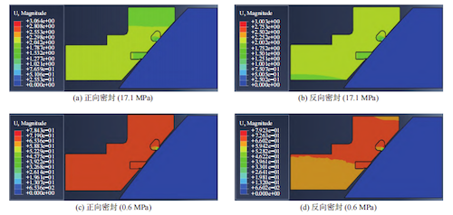
Figure 8 shows the deformation cloud diagrams of the sealing assembly under forward and reverse sealing conditions at both high and low pressures. As illustrated, regardless of the pressure condition, the maximum deformation in both forward and reverse sealing occurs at the valve seat sealing ring where it contacts the upper right corner of the valve seat support ring. Under high-pressure sealing, the maximum deformation of the valve seat sealing ring is approximately 3 mm. The normal compression deformation between the valve seat sealing ring and the ball is about 1.03 mm and 0.95 mm, respectively. Under low-pressure sealing, the maximum deformation of the valve seat sealing ring is about 0.78 mm and 0.80 mm, with normal compression deformation at the contact surface between the valve seat sealing ring and the ball being approximately 0.39 mm and 0.38 mm, respectively. At low pressure, the contact area of the valve seat sealing ring is significantly reduced. Therefore, it is important to ensure that the medium’s working pressure exceeds the design pressure to maintain effective sealing performance.
(a) Forward seal (17.1 MPa) (b) Reverse seal (17.1 MPa) (c) Forward seal (0.6 MPa) (d) Reverse seal (0.6 MPa)
Figure 8 Deformation of ball valve seal assembly
Within the pressure range considered, the high-stress area during forward sealing appears at the upper right contact corner between the valve seat support ring and the valve seat sealing ring, while during reverse sealing, it shifts to the lower left arc angle. In both cases, the stress remains below the yield strength of the valve seat support ring, ensuring no yield deformation occurs.
- Under high-pressure sealing conditions, the maximum stress on the sealing ring occurs at the two sharp corners in contact with the valve seat support ring, regardless of whether the sealing is forward or reverse. In forward sealing, stress concentration is primarily at the upper right corner, while in reverse sealing, elevated stress is present at both sharp corners. To reduce the risk of failure, increasing the chamfer radius at these corners can help alleviate stress concentration and minimize deformation in the valve seat support ring.
- In both forward and reverse sealing, the contact pressure between the valve seat sealing ring and the ball under high-pressure conditions exceeds the medium pressure, ensuring reliable sealing performance. Under low-pressure conditions, although the contact pressure remains higher than the medium pressure, the contact area is reduced and the pressure distribution becomes more uneven. Therefore, it is critical to maintain a working pressure above the design pressure to avoid degradation of sealing performance caused by insufficient medium pressure.
- Although this study evaluates the sealing performance of the ball valve assembly under static pressure conditions, in practical applications, damage to the sealing components is often attributed to excessive friction during valve operation. Therefore, further investigation is required into the deformation and wear of the sealing elements caused by ball rotation.